- 您现在的位置:买卖IC网 > Sheet目录3813 > PIC18F452-I/ML (Microchip Technology)IC MCU FLASH 16KX16 A/D 44QFN
1997 Microchip Technology Inc.
DS30444E - page 47
PIC16C9XX
7.2
Using Timer0 with an External Clock
When an external clock input is used for Timer0, it must
meet certain requirements. The requirements ensure
the external clock can be synchronized with the internal
phase clock (TOSC). Also, there is a delay in the actual
incrementing of Timer0 after synchronization.
7.2.1
EXTERNAL CLOCK SYNCHRONIZATION
When no prescaler is used, the external clock input is
the same as the prescaler output. The synchronization
of T0CKI with the internal phase clocks is accom-
plished by sampling the prescaler output on the Q2 and
Q4 cycles of the internal phase clocks (Figure 7-5).
Therefore, it is necessary for T0CKI to be high for at
least 2Tosc (and a small RC delay of 20 ns) and low for
at least 2Tosc (and a small RC delay of 20 ns). Refer to
the electrical specication of the desired device.
When a prescaler is used, the external clock input is
divided by the asynchronous ripple-counter type pres-
caler so that the prescaler output is symmetrical. For
the external clock to meet the sampling requirement,
the ripple-counter must be taken into account. There-
fore, it is necessary for T0CKI to have a period of at
least 4Tosc (and a small RC delay of 40 ns) divided by
the prescaler value. The only requirement on T0CKI
high and low time is that they do not violate the mini-
mum pulse width requirement of 10 ns. Refer to param-
eters 40, 41 and 42 in the electrical specication of the
desired device.
7.2.2
TMR0 INCREMENT DELAY
Since the prescaler output is synchronized with the
internal clocks, there is a small delay from the time the
external clock edge occurs to the time the Timer0 mod-
ule is actually incremented. Figure 7-5 shows the delay
from the external clock edge to the timer incrementing.
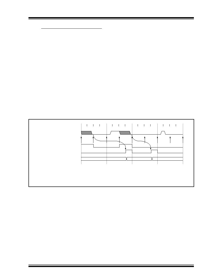
FIGURE 7-5:
TIMER0 TIMING WITH EXTERNAL CLOCK
Q1
Q2 Q3 Q4
Q1 Q2 Q3 Q4
External Clock Input or
Prescaler output (2)
External Clock/Prescaler
Output after sampling
Increment Timer0 (Q4)
Timer0
T0
T0 + 1
T0 + 2
Small pulse
misses sampling
Note 1: Delay from clock input change to Timer0 increment is 3Tosc to 7Tosc. (Duration of Q = Tosc).
Therefore, the error in measuring the interval between two edges on Timer0 input =
±4Tosc max.
2: External clock if no prescaler selected, Prescaler output otherwise.
3: The arrows indicate the points in time where sampling occurs.
(3)
(1)
发布紧急采购,3分钟左右您将得到回复。
相关PDF资料
PIC18F452-I/PT
IC MCU FLASH 16KX16 EE 44TQFP
PIC18F6622-I/PT
IC PIC MCU FLASH 32KX16 64TQFP
201828-1
CONN JACKSCREW SHORT-SHORT FMALE
608489070001049
CONN CONTACT FOR 8483/8484 PLUGS
PIC18LF258-I/SO
IC MCU CAN FLASH 16K LP 28-SOIC
DSPIC33FJ256GP710-I/PT
IC DSPIC MCU/DSP 256K 100TQFP
9-1469373-9
CONN GUIDE MOD FEMALE R/A
PIC32MX460F256L-80V/PT
IC MCU 32BIT 256KB FLASH 100TQFP
相关代理商/技术参数
PIC18F452-I/P
功能描述:8位微控制器 -MCU 32KB 1536 RAM 34I/O RoHS:否 制造商:Silicon Labs 核心:8051 处理器系列:C8051F39x 数据总线宽度:8 bit 最大时钟频率:50 MHz 程序存储器大小:16 KB 数据 RAM 大小:1 KB 片上 ADC:Yes 工作电源电压:1.8 V to 3.6 V 工作温度范围:- 40 C to + 105 C 封装 / 箱体:QFN-20 安装风格:SMD/SMT
PIC18F452-I/P
制造商:Microchip Technology Inc 功能描述:IC 8BIT FLASH MCU 18F452 DIP40
PIC18F452-I/PG
功能描述:8位微控制器 -MCU 32KB 1536 RAM 34I/O RoHS:否 制造商:Silicon Labs 核心:8051 处理器系列:C8051F39x 数据总线宽度:8 bit 最大时钟频率:50 MHz 程序存储器大小:16 KB 数据 RAM 大小:1 KB 片上 ADC:Yes 工作电源电压:1.8 V to 3.6 V 工作温度范围:- 40 C to + 105 C 封装 / 箱体:QFN-20 安装风格:SMD/SMT
PIC18F452-I/PT
功能描述:8位微控制器 -MCU 32KB 1536 RAM 34I/O RoHS:否 制造商:Silicon Labs 核心:8051 处理器系列:C8051F39x 数据总线宽度:8 bit 最大时钟频率:50 MHz 程序存储器大小:16 KB 数据 RAM 大小:1 KB 片上 ADC:Yes 工作电源电压:1.8 V to 3.6 V 工作温度范围:- 40 C to + 105 C 封装 / 箱体:QFN-20 安装风格:SMD/SMT
PIC18F452-I/PT
制造商:Microchip Technology Inc 功能描述:8BIT FLASH MCU SMD 18F452 TQFP44
PIC18F452-I/PTC28
制造商:Microchip Technology Inc 功能描述:
PIC18F452-I/PTG
功能描述:8位微控制器 -MCU 32KB 1536 RAM 34I/O RoHS:否 制造商:Silicon Labs 核心:8051 处理器系列:C8051F39x 数据总线宽度:8 bit 最大时钟频率:50 MHz 程序存储器大小:16 KB 数据 RAM 大小:1 KB 片上 ADC:Yes 工作电源电压:1.8 V to 3.6 V 工作温度范围:- 40 C to + 105 C 封装 / 箱体:QFN-20 安装风格:SMD/SMT
PIC18F452IL
制造商:Microchip Technology Inc 功能描述: